3D Surfaces
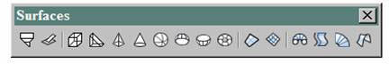
3D Surfaces
2D solid
3D Face
Box
Wedge
Pyramid
Cone
Sphere
Dome
Dish
Torus
Edge
Mesh
Revolved Surface
Tabulated Surface
Ruled Surface
Edge Surface
A MESH represents
an object's surface using planar facets. The mesh density, or number of facets,
is defined in terms of a matrix of M
and N vertices, similar to a grid consisting of
columns and rows. M and N
specify the column and row position, respectively, of any given vertex. You can
create meshes in both 2D and 3D, but they are used
primarily for 3D.
Use meshes if you
need hiding, shading, and rendering capabilities that wireframes
don't provide but do not need the physical properties that solids provide
(mass, weight, center of gravity, and so on). Meshes are also useful if you
want to create geometry with unusual mesh patterns, such as a 3D topographical
model of mountainous terrain.
A mesh can be open
or closed. A mesh is open in a given direction if the start and end edges of the mesh do not touch, as shown
in the following illustrations.
AutoCAD provides
several methods for creating meshes. You can enter the mesh parameters manually
or use the 3D
command, which simplifies the process of creating the basic surface shapes.
The 3D command creates the following 3D shapes: boxes,
cones, dishes, domes, meshes, pyramids, spheres, tori
(donuts), and wedges. These are meshes that are displayed as wireframes until you use HIDE, RENDER, or SHADEMODE. To view the objects you are creating with the
3D command more clearly, set a viewing direction
with 3DORBIT, DVIEW, or VPOINT. The procedures for creating 3D shapes are
similar to those for creating 3D solids.
In the following illustrations, the numbers indicate points you
specify to create the mesh.
3DMESH
AutoCAD defines a polygon mesh by a
matrix, the size of which is determined by M and N size
values. M × N equals the number of
vertices that you must specify.
Specify location for vertex (0, 0): Enter a 2D or 3D
coordinate. AutoCAD defines the location of each vertex
in the mesh by m and n, the
row and column indices of the vertex. The limit is between 2 and 256 virtex

Create
a Rectangular Mesh
With the 3DMESH command, you can create polygon meshes that are
open in both the M and N
directions (similar to the X and Y axes of an XY plane).
You can close the meshes with PEDIT. You can use 3DMESH
to construct very irregular surfaces. In most cases, you can use 3DMESH in conjunction with scripts or AutoLISP routines when you know the mesh points.
The PFACE command produces a polyface
(polygon) mesh, with each face capable of having numerous vertices.
Creating a polyface mesh is similar to
creating a rectangular mesh. To create a polyface
mesh, you specify coordinates for its vertices. You then define each face by
entering vertex numbers for all the vertices of that face. As you create the polyface mesh, you can set specific edges to be invisible,
assign them to layers, or give them colors.
To make the edge invisible, enter the vertex
number as a negative value.
![]()
You can control the display of invisible edges with the SPLFRAME system variable. If SPLFRAME
is set to a nonzero value, the invisible edges become
visible and can then be edited. If SPLFRAME is set
to 0, the invisible edges remain invisible.
With RULESURF, you can create a surface mesh between two
objects. You use two different objects to define the edges of the ruled
surface: lines, points, arcs, circles, ellipses, elliptical arcs, 2D polylines, 3D polylines, or splines. Pairs of objects to be used
as the "rails" of a ruled surface mesh must both be either open or
closed. You can pair a point object with either an open or a closed object.
You
can specify any two points on closed curves to complete RULESURF.
For open curves, AutoCAD starts construction of the ruled surface based on the
locations of the specified points on the curves.
Create
a Tabulated Surface Mesh
With the TABSURF command, you can create a surface mesh
representing a general tabulated surface defined by a path curve and a
direction vector. The path curve can be a line, arc, circle, ellipse,
elliptical arc, 2D polyline, 3D polyline,
or spline. The direction vector can be a line or an
open 2D or 3D polyline. TABSURF
creates the mesh as a series of parallel polygons running along a specified
path. You must have the original object and the direction vector already drawn,
as shown in the following illustrations.
Create
a Surface of Revolution Mesh
Use the REVSURF command to create a surface of revolution by
rotating a profile of the object about an axis. The axis can be a line or
straight PLINE. The Profile can be a
LINE, ARC, CIRCLE, PLINE, or SPLINE. REVSURF is useful for surfaces with rotational symmetry.
Changes in SURFTAB1 (n) and SURFTAB2 (n)
control the smoothness of the surface.
The default is n = 6.
Create
an Edge-Defined Surface Mesh
With the EDGESURF command, you can create a Coons
surface patch mesh, as shown in the following illustration, from four
objects called edges. Edges can be arcs, lines, polylines, splines, and
elliptical arcs. They MUST form a closed
loop and share endpoints. A Coons patch is a bicubic surface (one curve in the M
direction and another in the N direction)
interpolated between the four edges. Changes in SURFTAB1 (n) and SURFTAB2 (n)
control the smoothness of the surface.
The default is n = 6.
The variable SURFTYPE
controls the tyoe of mathematical formula used to
generate the meshes; SURFTYPE (5) uses a Quadratic B-Spline,
SURFTYPE (6)uses a Cubic B-Spline
and is the default, SURFTYPE (8) uses a Bezier Curve.